

Industrial equipment manufacturers rely on precision stamped metal parts for components that must maintain dimensional accuracy across thousands of production cycles. From pump housings and valve components to gear systems and hydraulic manifolds, precision stamped metal parts deliver the dimensional repeatability that industrial equipment designers need to assemble complex systems with predictable performance. This article examines precision stamped metal parts from a design engineering and procurement perspective, covering the tolerance capabilities, material selection criteria, tooling strategies, and quality assurance protocols that ensure precision stamped metal parts meet the demanding requirements of industrial equipment applications.
Understanding Precision in Stamped Metal Parts for Industrial Equipment
The term "precision" in precision stamped metal parts refers to the tolerance band within which the stamped component must consistently fall. Unlike general industrial stamping where tolerances of ±0.010 to ±0.030 inches are acceptable, precision stamped metal parts for industrial equipment typically require feature tolerances of ±0.001 to ±0.005 inches for critical dimensions, with the tightest precision stamping applications approaching ±0.0005 inches on specific features. Achieving this precision requires not only precision-ground dies and servo-controlled presses but also a holistic approach to process control that accounts for material thickness variation, springback, tool wear, and thermal effects during production.
Dimensional Repeatability Metrics in Precision Stamping
The most important metric for precision stamped metal parts in industrial equipment is not the initial dimensional measurement—it is the Cpk value that quantifies the process capability to maintain that dimension across the full production run. For critical features on precision stamped metal parts, a Cpk above 1.33 is the minimum acceptable standard, indicating that the process is running well within tolerance limits with a predicted non-conformance rate below 1 in 14,000 parts. Cpk above 1.67—required for certain automotive and aerospace precision stamped metal parts—indicates a process with exceptional capability where the natural variation of the process occupies less than 60 percent of the tolerance band. Buyers specifying precision stamped metal parts should request Cpk data on the three most critical dimensions from the supplier's production validation run as evidence of process capability.
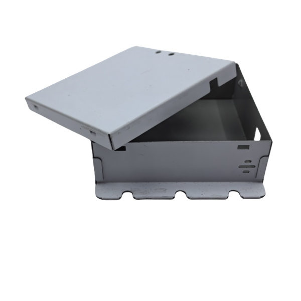
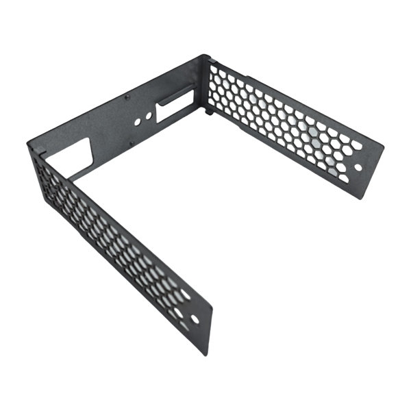
Material Selection for Precision Stamped Metal Parts
Material selection for precision stamped metal parts in industrial equipment is governed by three factors: the thickness uniformity of the incoming sheet or coil, the strain hardening rate of the material during forming, and the dimensional stability of the material after stamping. These requirements often drive material selection toward narrower bands of specification than general industrial stamping permits.
Thickness Tolerance Requirements for Precision Stamping
Precision stamped metal parts require incoming material thickness held to tighter tolerances than general-purpose commercial sheet. Where a commercial carbon steel supplier certifies material to ±0.005 inches thickness tolerance on 0.060-inch sheet, precision stamped metal parts suppliers specify strip to ±0.001 to ±0.002 inches thickness tolerance through negotiation with the steel service center or mill. This tighter material thickness specification adds a material cost premium of 10 to 25 percent but is essential for precision stamped metal parts because the blanking force—hence the cut edge quality and positional accuracy of the stamped features—is directly proportional to material thickness. A 0.005-inch thickness variation across the coil width produces corresponding variation in blanking force, which translates into variation in edge break radius, burr height, and feature position on every precision stamped metal parts component produced from that material lot.
Springback Compensation in Precision Stamped Metal Parts
Springback—the elastic recovery of the material after the forming pressure is released—is the primary dimensional stability challenge in precision stamped metal parts. The springback angle is a function of the material's yield strength, thickness, and the bend radius-to-thickness ratio. For precision stamped metal parts in high-strength materials, the springback compensation must be built into the die geometry by 2 to 5 degrees of overbend in high-tensile materials such as 301 stainless or AHSS. Controlling springback in precision stamped metal parts also requires maintaining consistent material yield strength across the production run, because springback compensation dialed into the die design is calibrated for a specific yield strength value, and yield strength variation of more than ±5 percent across material lots produces observable dimensional variation in the springback-sensitive features of precision stamped metal parts.
Tooling Technology for Precision Stamped Metal Parts
Tooling performance is the dominant variable determining dimensional quality in precision stamped metal parts. The die components—punch, die, stripper, and draw ring geometry—must be manufactured to tolerances tighter than the component tolerances they are designed to produce, requiring tool steel working surfaces machined to ±0.0002 inches and assembled with alignment verified by optical measurement systems.
Die Clearance and Edge Quality in Precision Metal Parts
Die clearance—the radial gap between punch and die—directly determines the cut edge quality and positional accuracy of precision stamped metal parts. Optimal die clearance for precision stamped metal parts is 3 to 6 percent of material thickness per side for carbon steel and 4 to 8 percent for stainless steel, compared to 8 to 15 percent for general industrial stamping. Tighter clearance produces a cut edge with a smaller rollover depth, increased burnish percentage, and reduced die break height—all quality attributes that improve the edge quality and positional accuracy of precision stamped metal parts. However, tighter clearance also increases the blanking force by 15 to 30 percent, accelerating punch wear and requiring more frequent tool replacement intervals. The optimal clearance for precision stamped metal parts is determined empirically for each material grade-thickness combination, balancing edge quality requirements against tool life economics.
Precision Tooling Materials and Coatings
Tooling materials for precision stamped metal parts production are specified for wear resistance and dimensional stability over extended production runs. Powder metal tool steels (PM23, PM60) provide superior wear resistance to conventional tool steels for high-volume precision stamped metal parts due to their uniform carbide distribution and higher hardness—64 to 68 HRC compared to 58 to 62 HRC for conventional D2 or A2 tool steel. Carbide and CBN (cubic boron nitride) inserts at piercing stations in progressive dies producing precision stamped metal parts achieve production intervals between regrinds of 1,000,000 to 5,000,000 strokes, compared to 50,000 to 200,000 strokes for conventional high-speed steel round punches in similar applications.
Quality Assurance for Precision Stamped Metal Parts
Quality assurance for precision stamped metal parts must keep pace with the tighter tolerances of precision production. Statistical process control integrated into the production process provides the feedback loop that detects tool wear or material variation before the dimensions drift outside specification.
In-Process Dimensional Verification Systems
Modern precision stamped metal parts production integrates in-process dimensional verification through vision inspection cameras, laser scanning systems, or CMM sampling that measures critical dimensions at predetermined intervals during the production run. In-process inspection for precision stamped metal parts catches dimensional drift before it produces non-conforming parts, enabling the press operator to adjust process parameters or replace worn tooling while the process is still running. This real-time dimensional feedback distinguishes precision stamping operations from general stamping, where post-production inspection may detect non-conforming parts only after a significant quantity has been produced and the root cause is weeks old.
Conclusion
Precision stamped metal parts for industrial equipment require a manufacturing system that integrates tight-tolerance incoming material, precision-ground die tooling with optimized clearance, springback-compensated die geometry, and in-process dimensional verification into a coherent production process. The Cpk metric quantifies process capability better than any single dimensional measurement, and precision stamped metal parts suppliers should be qualified based on documented process capability data rather than a single first article measurement. Industrial equipment manufacturers who source precision stamped metal parts from suppliers with demonstrated precision stamping capability—verified by Cpk data, die clearance optimization documentation, and in-process inspection systems—achieve assembly-level quality and reliability that general stamping suppliers cannot match.
Frequently Asked Questions
What tolerance can precision stamped metal parts achieve?
Precision stamped metal parts for industrial equipment achieve feature tolerances of ±0.001 to ±0.005 inches on stamped features, with the tightest precision applications approaching ±0.0005 inches on specific dimensions in ultra-precision stamping.
What die clearance is used for precision stamped metal parts?
Precision stamped metal parts use die clearances of 3 to 6 percent of material thickness per side for carbon steel and 4 to 8 percent for stainless steel—tighter than the 8 to 15 percent used in general industrial stamping.
How is process capability verified for precision stamped metal parts?
Process capability for precision stamped metal parts is verified through Cpk analysis on critical dimensions from a production validation run, with Cpk values above 1.33 indicating a capable process. Cp and Cpk are the statistical metrics that quantify whether the stamping process maintains dimensions within the specified tolerance band.
What material thickness tolerance is required for precision stamped metal parts?
Precision stamped metal parts require incoming material thickness held to ±0.001 to ±0.002 inches—significantly tighter than the ±0.005 inches typical of general commercial sheet material—to maintain blanking force consistency and feature positional accuracy across the production run.
References
1. ASM Handbook Volume 14B: "Sheet Metal Forming," ASM International, Materials Park, 2005.
2. Automotive Industry Action Group (AIAG), "Statistical Process Control (SPC)," 2nd Edition, AIAG, Southfield, 2005.
3. Lange, K., "Handbook of Metal Forming," 2nd Edition, McGraw-Hill, New York, 1985.
4. Hosford, W.F. and Caddell, R.M., "Metal Forming: Mechanics and Metallurgy," 4th Edition, Cambridge University Press, Cambridge, 2011.
5. Montgomery, D.C., "Introduction to Statistical Quality Control," 7th Edition, Wiley, Hoboken, 2012.