

An industrial sheet metal chassis is the structural skeleton of virtually every piece of industrial electronic equipment — the framework that holds circuit boards, power supplies, cooling fans, connectors, and control panels in precise alignment while protecting them from mechanical shock, electromagnetic interference, and environmental contamination. The quality of an industrial sheet metal chassis directly affects the equipment's reliability, serviceability, and regulatory compliance. For B2B buyers and design engineers specifying industrial sheet metal chassis for new products or sourcing replacements for existing equipment, understanding the manufacturing process — from design optimization through final inspection — is essential to producing a chassis that performs reliably across its intended service life.
Design Considerations for Industrial Sheet Metal Chassis
The design of an industrial sheet metal chassis begins with a clear definition of what the chassis must accomplish structurally and functionally. A chassis for a rack-mounted server must support the weight of dense electronic components while maintaining precise alignment of front-panel connectors to the rack cutout. A chassis for an outdoor power inverter must resist corrosion, provide thermal management for heat-generating components, and maintain gasket sealing under wind load and thermal cycling. A chassis for a mobile medical device must be lightweight, smooth-surfaced for cleaning, and structurally rigid enough to survive drop impacts. Each of these industrial sheet metal chassis applications drives different design decisions — and the chassis manufacturer's engineering team should be involved early enough in the design process to provide input on manufacturability and cost.
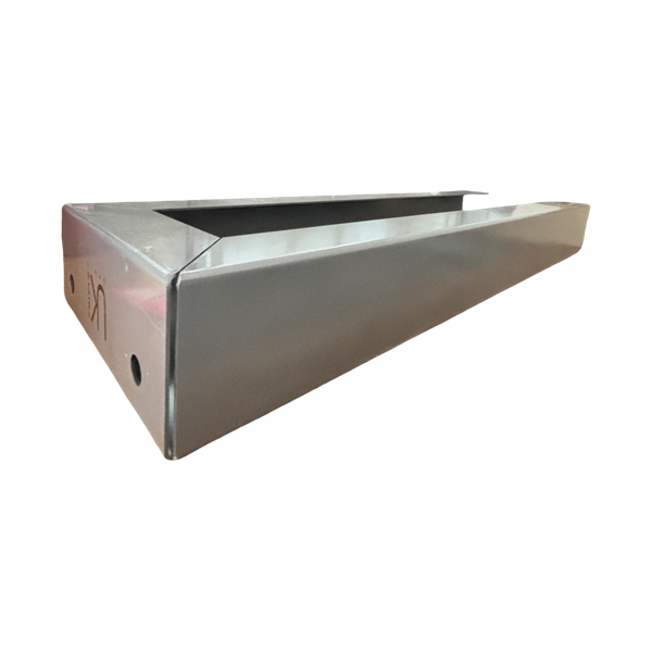
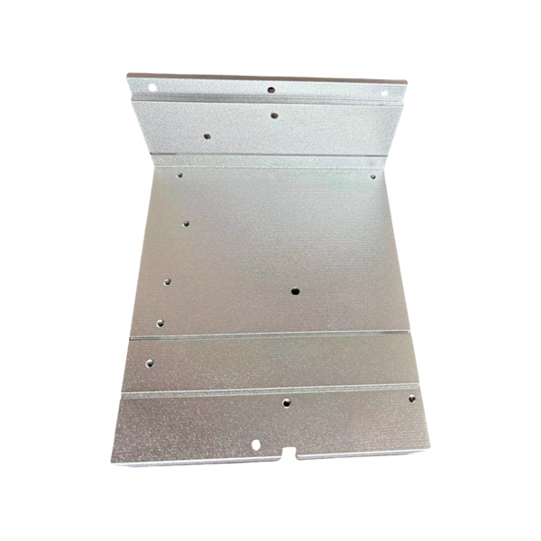
Design for Manufacturability in Sheet Metal Chassis Production
Design for manufacturability (DFM) for industrial sheet metal chassis focuses on features that can be produced efficiently on standard fabrication equipment. Minimum bend radii should be at least equal to the material thickness — a 0.060 inch bend radius on 0.060 inch material — to prevent cracking during forming. Hole diameters should be at least equal to material thickness for standard punching, or 0.020 inches minimum for laser cutting. Bend relief — small notches at the end of a bend line where a flange meets an adjacent face — prevents material tearing at the bend intersection and is a standard DFM feature on industrial sheet metal chassis designs. A chassis manufacturer that provides DFM feedback during the design phase identifies these features before tooling is committed, reducing the risk of costly design revisions after production begins.
Material Selection for Industrial Sheet Metal Chassis
The material for an industrial sheet metal chassis is selected based on structural requirements, weight constraints, corrosion environment, and cost. The most commonly specified materials are:
Cold-rolled steel (SPCC, CR1) — the economical baseline for indoor industrial sheet metal chassis applications where the chassis is painted or powder coated after fabrication. Typical thickness range: 0.040 to 0.125 inch.
Galvanized steel (SGCC) — specified for industrial sheet metal chassis in mildly corrosive environments where the zinc coating provides corrosion protection without painting. Typical thickness: 0.040 to 0.090 inch.
Aluminum (5052-H32, 6061-T6) — selected for industrial sheet metal chassis where weight reduction is critical or where the chassis serves as a heat sink for internal electronics. Typical thickness: 0.050 to 0.125 inch.
Stainless steel (304, 316L) — specified for industrial sheet metal chassis in corrosive environments, food processing, medical equipment, or outdoor installations. Typical thickness: 0.040 to 0.090 inch.
Each material has different forming characteristics, welding requirements, and surface finishing options that affect the industrial sheet metal chassis manufacturing process and cost. The chassis manufacturer should confirm material availability and pricing before the design is finalized — material specification changes after tooling is committed can delay production by weeks.
Fabrication Process for Industrial Sheet Metal Chassis
The industrial sheet metal chassis manufacturing process follows a sequence of cutting, forming, joining, and finishing operations. Each stage builds on the dimensional accuracy established in the previous stage — and tolerance accumulation across stages must be managed to ensure the final chassis assembly meets the specified dimensions.
Cutting Operations for Sheet Metal Chassis
Fiber laser cutting is the standard cutting method for industrial sheet metal chassis production. The laser cuts the chassis flat pattern from sheet stock — including all panel cutouts for connectors, ventilation slots, mounting holes, and cable pass-throughs — in a single operation. Positional accuracy of ±0.003 to ±0.005 inches on laser-cut features ensures that mounting holes for internal components align with the components' fixturing requirements. For industrial sheet metal chassis produced in high volumes, CNC turret punching may supplement or replace laser cutting for standard hole patterns — combining the speed of punching with the flexibility of laser cutting on the same part through sequential operations.
Bending and Forming for Sheet Metal Chassis Geometry
CNC press brake bending forms the flat-cut pattern into the three-dimensional industrial sheet metal chassis shape. A typical chassis requires 4 to 12 bends — flanges on the top and bottom panels, side-wall bends, mounting tab bends, and internal component bracket bends. Each bend introduces springback that the CNC controller compensates for based on stored material parameters. For industrial sheet metal chassis with complex multi-bend geometries, the bending sequence matters: bends that constrain access for later bends must be performed in the correct order, and the chassis manufacturer's process engineer plans this sequence during the production planning phase.
Joining Methods for Industrial Sheet Metal Chassis
The formed panels of an industrial sheet metal chassis must be joined into a rigid assembly. The joining method depends on the material, the structural requirements, and whether the chassis must be sealed against environmental ingress.
Welding for Structural Chassis Assemblies
TIG welding is the standard joining method for industrial sheet metal chassis in stainless steel and aluminum, producing clean welds with minimal heat input that preserves the dimensional accuracy of the formed panels. MIG welding is used for carbon steel chassis where higher deposition rate is advantageous. Spot welding — resistance welding at intervals along the joint line — is used for industrial sheet metal chassis where the joint does not need to be sealed or cosmetically finished, typically on internal bracket-to-panel connections. Welded industrial sheet metal chassis joints must be inspected visually per AWS standards, and structural welds on load-bearing chassis may require additional non-destructive testing.
Hardware Insertion and Fastener Assembly
Many industrial sheet metal chassis designs use mechanical fasteners — PEM inserts (self-clinching fasteners), rivet nuts, and threaded standoffs — to join panels and provide mounting points for internal components. PEM inserts are pressed into pre-punched holes in the sheet metal using a dedicated insertion press, providing permanent threaded mounting points that are stronger and more reliable than tapped sheet metal threads. For industrial sheet metal chassis that must be disassembled for service, fastener joints allow panel removal without destroying the chassis — a design requirement for equipment that requires field maintenance.
Surface Finishing for Industrial Sheet Metal Chassis
The surface finish on an industrial sheet metal chassis provides corrosion protection and appearance. Powder coating is the standard finish for carbon steel industrial sheet metal chassis — providing a durable coating 1.5 to 3 mils thick that withstands 500 to 1,000 hours of salt spray per ASTM B117. The powder coating process includes chemical cleaning and iron phosphate or zinc phosphate conversion coating before powder application, ensuring adhesion that survives impact and thermal cycling without flaking. For aluminum industrial sheet metal chassis, chromate conversion coating provides electrical conductivity (for EMI shielding applications) and paint adhesion, while anodizing provides a harder, more durable surface for chassis exposed to handling wear.
EMI Shielding Considerations in Sheet Metal Chassis Design
For industrial sheet metal chassis housing electronic equipment that generates or is sensitive to electromagnetic interference, the chassis material and joint design affect EMI shielding effectiveness. Conductive metal-to-metal contact at panel joints — achieved through welded seams, conductive gaskets, or EMI shielding fingers at door and panel interfaces — creates a Faraday cage that attenuates electromagnetic radiation. Powder coating and paint are insulators that can degrade EMI shielding at joints — a industrial sheet metal chassis design for EMI-sensitive applications may specify bare metal contact surfaces at critical joints, masked from coating during the finishing process.
Quality Verification for Industrial Sheet Metal Chassis
Quality verification for industrial sheet metal chassis includes dimensional inspection of the assembled chassis — checking that mounting hole patterns, panel-to-panel alignment, and overall envelope dimensions meet drawing tolerances — and functional verification that internal components fit and mount correctly. A first article inspection report documents the dimensional verification of every specified characteristic, and a fit check with actual internal components — circuit boards, power supplies, connectors — confirms that the chassis design accommodates the components as intended. For industrial sheet metal chassis in regulated applications, the quality documentation package also includes material test reports, welding procedure specifications, and finishing system certifications.
Conclusion
An industrial sheet metal chassis is a system-level component whose quality affects the performance, reliability, and regulatory compliance of the equipment it supports. The chassis manufacturing process — laser cutting, CNC bending, welding or fastener assembly, and surface finishing — must be executed with process control at each stage to produce a chassis that meets dimensional, structural, and environmental requirements consistently. B2B buyers sourcing industrial sheet metal chassis should work with a manufacturer that provides DFM feedback during design, maintains documented process capability on critical dimensions, offers the material and finishing options the application requires, and produces the quality documentation that the OEM's quality system demands. A chassis manufacturer with integrated fabrication capability — from cutting through finishing under one roof, with ISO 9001 quality system certification — provides the process control and documentation infrastructure that industrial sheet metal chassis production requires. If you are designing or sourcing an industrial sheet metal chassis for your next product, engage your fabrication partner early in the design phase, request a DFM review, and verify quality system capability before committing to production — the result is a chassis that supports your product's performance and reliability throughout its service life.
FAQ
What material is best for an industrial sheet metal chassis?
Cold-rolled steel is the economical baseline for indoor industrial sheet metal chassis applications. Aluminum (5052-H32) is specified for weight-sensitive or thermal management applications. Stainless steel (304 or 316L) is used for corrosive or hygienic environments.
What thickness is typical for industrial sheet metal chassis?
Typical industrial sheet metal chassis material thickness ranges from 0.040 to 0.125 inch depending on the structural requirements, chassis size, and material type. Larger chassis or higher-load applications use thicker material with internal reinforcements.
How is EMI shielding achieved in sheet metal chassis?
Industrial sheet metal chassis EMI shielding is achieved through conductive metal-to-metal contact at panel joints — using welded seams, conductive gaskets, or EMI shielding fingers. Coating on contact surfaces must be masked to maintain electrical conductivity at critical joints.
What surface finish is recommended for industrial sheet metal chassis?
Powder coating is the standard finish for carbon steel industrial sheet metal chassis, providing 500 to 1,000 hours salt spray resistance. Aluminum chassis use chromate conversion coating for paint adhesion and electrical conductivity, or anodizing for surface hardness.
Can a sheet metal chassis manufacturer handle both design and production?
Yes. An experienced industrial sheet metal chassis manufacturer provides DFM feedback during the design phase, then produces the chassis through integrated cutting, bending, welding, and finishing operations — reducing coordination risk and ensuring design intent translates to production reality.
References
1. IEEE Std 1302-2013, "IEEE Guide for the Electromagnetic Characterization of Conductive Gaskets," Institute of Electrical and Electronics Engineers, Piscataway, 2013.
2. ASTM B117-2019, "Standard Practice for Operating Salt Spray (Fog) Apparatus," ASTM International, West Conshohocken, 2019.
3. IEC 61000-5-7:2001, "Electromagnetic Compatibility (EMC) — Installation and Mitigation Guidelines — Degrees of Protection Provided by Enclosures Against Electromagnetic Disturbances," International Electrotechnical Commission, Geneva, 2001.
4. Kalpakjian, S. and Schmid, S.R., "Manufacturing Engineering and Technology," 7th Edition, Pearson, Upper Saddle River, 2017.
5. ISO 9001:2015, "Quality Management Systems—Requirements," International Organization for Standardization, Geneva, 2015.