

Speed to market determines competitive advantage in manufacturing, and CNC prototype machining is the primary enabler of fast product development cycles. Whether validating a new product design, proving out a manufacturing process, or producing functional prototypes for customer evaluation, CNC prototype machining delivers production-quality parts in days rather than the weeks or months required for permanent tooling. Understanding how to specify, prioritize, and optimize CNC prototype machining enables product development teams to compress their design-build-test cycles without sacrificing the accuracy that makes prototyping valuable.
Why CNC Prototype Machining Outperforms Additive Prototyping
CNC prototype machining produces parts from the same material grades, heat treatments, and surface finishes that will be used in final production—a capability that additive manufacturing and rapid casting processes cannot replicate. A CNC prototype machining 316L stainless steel bracket machined from a production-grade bar has the same mechanical properties, corrosion resistance, and dimensional accuracy as the production part that will eventually be cast, stamped, or fabricated at volume. This material fidelity is the difference between a prototype that validates form and one that validates form, fit, and function—including the mechanical and environmental testing required for regulatory submissions and customer qualification approvals.
Material Fidelity for Functional Testing
CNC prototype machining enables functional testing under actual service conditions because the prototype parts share the same material chemistry, heat treatment condition, and surface finish as final production components. When a design requires fatigue testing per ASTM E466 or pressure testing per ASME B31.3, CNC prototype machining is the only prototyping method that produces test articles with material properties representative of the final production state. Parts produced by additive manufacturing, urethane casting, or injection molding from prototype tooling have different microstructures, residual stress states, and surface characteristics than production-equivalent CNC prototype machining components, and they may produce test results that do not translate to the production environment.
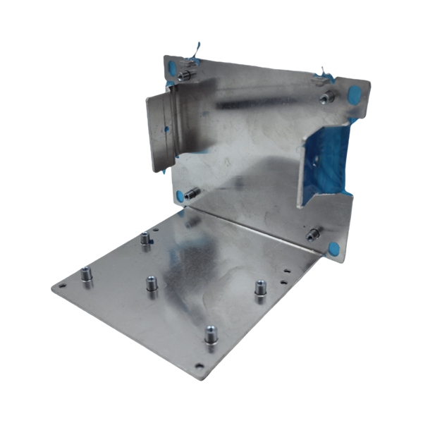
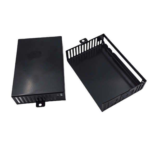
Process Optimization for Fast CNC Prototype Machining
CNC prototype machining requires a different process engineering approach than production machining. Production machining optimizes for minimum cost per part through tool life maximization, cycle time reduction, and fixture amortization across thousands of parts. CNC prototype machining optimizes for minimum time-to-part through aggressive cutting parameters, high material removal rates, and generich fixturing systems that eliminate custom fixture lead time.
Aggressive Cutting Parameters for CNC Prototype Machining
CNC prototype machining employs cutting speeds and feed rates optimized for material removal rate, not tool life. For aluminum CNC prototype machining, feed rates 20 to 40 percent above production recommended parameters enable cycle time reductions of 30 to 50 percent while maintaining dimensional accuracy adequate for prototype verification. The tradeoff is accelerated tool wear and a higher risk of tool breakage, both acceptable in CNC prototype machining where the total cutting time per part is measured in minutes rather than the hours of cumulative production runtime. For stainless steel and titanium CNC prototype machining, the aggressive parameter approach requires more caution—exceeding critical chip load thresholds in these materials can cause work-hardening that damages the workpiece surface and produces out-of-tolerance features that invalidate the prototype.
Generic Fixturing Systems for CNC Prototype Machining
CNC prototype machining eliminates custom fixture fabrication—which typically requires 2 to 5 days for design and machining—by using generic fixture systems that locate and clamp workpiece blanks without part-specific tooling. Modular vice systems with interchangeable jaws, multi-station vacuum chuck platforms, and dovetail gripping systems enable CNC prototype machining of most prismatic geometries directly from flat stock or bar material without custom fixture fabrication. For CNC prototype machining of complex geometries that exceed the capability of generic fixturing, the prototype machinist uses double-sided tape, superglue, or soft jaw fixtures that are machined in minutes rather than hours, relying on the CNC prototype machining programmer's skill to accommodate the reduced rigidity of these temporary fixturing methods.
Material Options for CNC Prototype Machining
CNC prototype machining supports the full range of engineering materials available in bar, plate, or billet form, enabling prototype evaluation across any material family specified for final production. The most commonly specified materials for CNC prototype machining follow the general distribution of production machining: aluminum alloys (6061-T6, 7075-T6) for 40 to 50 percent of prototype work, stainless steels (304, 316L, 303) for 20 to 30 percent, and engineering polymers (Delrin, PEEK, polycarbonate) for 10 to 20 percent.
Near-Net Shape Blanks for CNC Prototype Machining Cost Reduction
For CNC prototype machining of large components where the volume of material removed from solid bar stock is excessive—producing a 2-pound finished part from a 15-pound billet—near-net shape blanks reduce both material cost and machining time. Saw-cut blanks, plasma-cut profiles, and waterjet-preformed shapes provide CNC prototype machining stock that approximates the final part geometry, reducing the roughing passes required to remove excess material. The time saved in roughing passes for CNC prototype machining of near-net shape blanks typically reduces total machining time by 30 to 50 percent, with proportional reductions in quoted cost for prototype quantities.
Design for CNC Prototype Machining: DFM Guidelines
Design for manufacturability (DFM) principles for CNC prototype machining differ from production DFM in several important respects. While production machining benefits from design features that minimize the number of setups, simplify tool access, and reduce cycle time through tool path optimization, CNC prototype machining can tolerate more complex setups and longer cycle times because the total production quantity is small and the setup cost per part is amortized over fewer parts.
Corner Radii and Tool Access for CNC Prototype Machining
The minimum internal corner radius in CNC prototype machining is determined by the tool diameter available in the shop. Standard CNC prototype machining tooling includes end mills down to 0.030 inches diameter, enabling internal corner radii of 0.015 inches minimum. Specifying internal corner radii below 0.030 inches for CNC prototype machining requires micro-tool tooling that operates at higher spindle speeds (20,000 to 50,000 RPM) and slower feed rates to prevent tool deflection and breakage, increasing cycle time by a factor of 2 to 5 compared to standard-tool CNC prototype machining. For prototype quantities where a 0.030-inch radius is visually acceptable and functionally adequate, specifying the larger radius reduces cost and accelerates delivery without meaningful impact on prototype evaluation quality.
Undercut and Deep Pocket Design for CNC Prototype Machining
Deep pockets in CNC prototype machining—defined as pockets with depth-to-diameter ratios exceeding 3:1—require extended-length tooling that is more susceptible to deflection, chatter, and breakage than standard-length tooling. For CNC prototype machining of prototype parts with deep pockets, specifying pocket width-to-depth ratios below 3:1 where possible reduces the tool deflection error that produces undersized internal features. When the design requires a deep pocket that exceeds this ratio, communicate to the CNC prototype machining service provider during the quoting phase so they can adjust their process parameters and include extended-length tooling cost in the quote rather than discovering the tooling requirement during after-award review.
Lead Time Optimization for CNC Prototype Machining
CNC prototype machining lead time ranges from 2 to 15 business days depending on part complexity, material availability, and the current capacity utilization of the machining service provider. For truly accelerated CNC prototype machining—where 24-hour delivery is required—the provider must have the part's material grade in stock, an available machine with the required axis count and work envelope, and a programmer available to generate the tool path immediately upon order receipt. Emergency CNC prototype machining delivery commands a premium of 50 to 100 percent above standard lead time pricing, reflecting the scheduling disruption and resource reallocation required to prioritize a single job over existing production commitments.
Conclusion
CNC prototype machining delivers production-quality parts in compressed timelines that enable fast product development cycles. The aggressive cutting parameters, generic fixturing systems, near-net shape blanks, and DFM-optimized designs that distinguish CNC prototype machining from production machining each contribute to reducing the time from CAD model to functional prototype. Product development teams who understand these process optimization strategies and communicate their prototype requirements clearly to CNC prototype machining service providers consistently achieve faster turnaround, lower prototyping cost, and better correlation between prototype and production component performance—compressing the development cycle that determines competitive advantage in manufacturing.
Frequently Asked Questions
How fast is CNC prototype machining turnaround?
Standard CNC prototype machining lead time ranges from 3 to 7 business days. Expedited CNC prototype machining with 24-hour delivery is available at a premium rate when the service provider has material in stock and available machine capacity.
What is the cost difference between CNC prototype machining and production machining?
CNC prototype machining per-part cost is typically 2 to 5 times higher than equivalent production machining at volume because the setup, programming, and first article inspection costs are amortized over fewer parts.
Can CNC prototype machining produce parts in the same material as final production?
Yes. CNC prototype machining produces parts from bar, plate, or billet stock in the same material grade, heat treatment condition, and surface finish as the final production component, enabling functionally representative testing.
What file formats are required for CNC prototype machining quoting?
Standard file formats for CNC prototype machining quotes include STEP (.stp) or IGES (.igs) for solid geometry and PDF engineering drawings with tolerance, material, and surface finish specifications.
References
1. ISO 9001:2015, "Quality Management Systems—Requirements," International Organization for Standardization, Geneva, 2015.
2. ASME Y14.5-2018, "Dimensioning and Tolerancing," American Society of Mechanical Engineers, New York, 2018.
3. Kalpakjian, S. and Schmid, S.R., "Manufacturing Engineering and Technology," 7th Edition, Pearson, Upper Saddle River, 2017.
4. Todd, R.H., Allen, D.K., and Alting, L., "Manufacturing Processes for Engineering Materials," 4th Edition, Pearson, Upper Saddle River, 1999.
5. ASTM E466-15, "Standard Practice for Conducting Force Controlled Constant Amplitude Axial Fatigue Tests of Metallic Materials," ASTM International, West Conshohocken, 2015.